OBJECTIVE
The main idea behind this simulation is to make students understand about working of logic gates, basic theory behind them and realizing of some simple Boolean expressions using them.
SCIENCE
Logic gates are basic building blocks of any digital circuits. Most of electronic devices have some form of logic gates inbuilt in them. In Digital electronics, logic circuits with one or more inputs and one output forms a gate. Gates are also available in the form of Integrated Circuits (ICs)
- Basic gates include: AND, OR, NOT, NAND, NOR, XOR, XNOR.
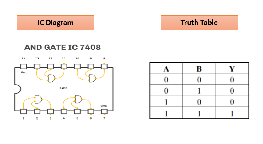
AND Gate: This gate performs logical multiplication operation. Here the output is low when
either of input is low and high when both the inputs are high. Basic Transistor- transistor logic
(TTL) AND gate IC is 7408 (pin diagram depicted below) it is named as quad 2 input AND gate
IC as it contains 4 nos. of AND gates.
Logic Expression: Y= A.B

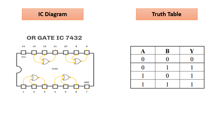
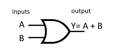
OR Gate: This gate performs logical addition operation. Here the output is low when both the
inputs are low and high when either of the input is high. Basic TTL OR gate IC is 7432 (pin
diagram depicted below) it is named as quad 2 input OR gate IC as it contains 4 OR gates.
Logic Expression: Y= A + B
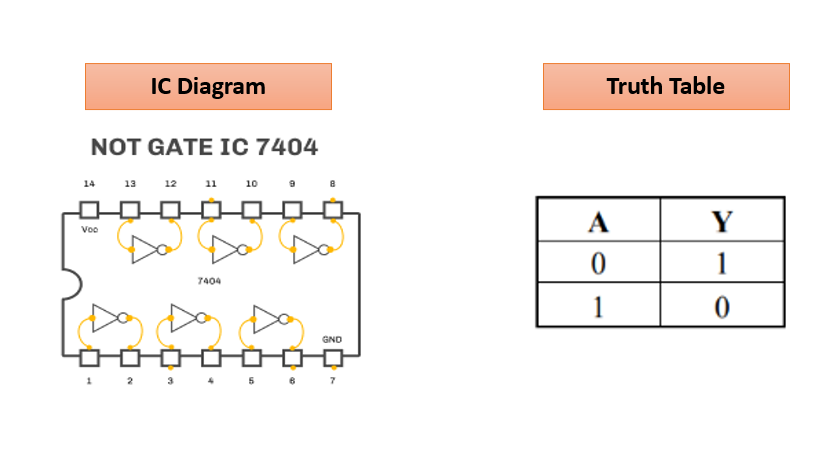
NOT Gate: This logic gate performs the function for switching from one logic level to another
i.e. complementation. Basic NOT gate IC is 7404 (hex inverter).
Logic Expression: Y= Ā

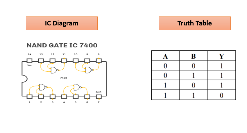
NAND Gate: It is nothing but an AND gate followed with a NOT gate. It is termed as Universal
gate. Its output is low if all the inputs are in logic high. Basic IC for NAND gate is 7400.
Logic Expression: Y= A • B

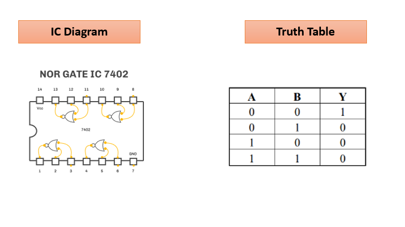
NOR Gate: It is nothing but an OR gate followed with a NOT gate. It is termed as Universal
gate. Its output is high if all the inputs are in logic low. Basic IC for NOR gate is 7402.
Logic Expression: Y= A + B

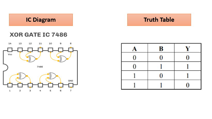
XOR Gate: It is also termed as exclusive OR gate and may be used as programmable inverter.
Its output is high if and only if one of the inputs is logic high. Basic IC for XOR gate is 7486.
Logic Expression: Y= A ⊕ B =(AB) + (AB)

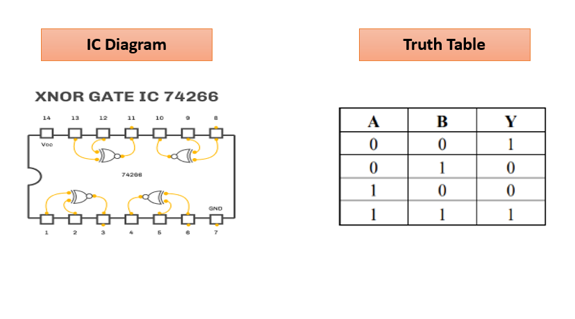
XNOR Gate: It is XOR gate followed with NOT gate and is also termed as equivalence gate. Its
output is high if both of the inputs are either logic high or logic low. Basic IC for XNOR gate is
IC 74266
Logic Expression: Y= A ⊙ B = A ⊕ B = AB + A B

SIGNIFICANCE
Logic gates are used for performing logical operations to get decisions based on combinations of two or more digital signals coming as their inputs. Hence they are used in decision making, for the development of many electronic circuits like in light activated burglar alarm, door bells, temperature detectors etc.
TUTORIAL
To understand the functioning of a gate, follow the steps below:
Steps:
- Select a gate to study, for example: NOT gate.
- Now pick the input, click on it and extend the connection to input of the gate.
- Now pick the output, click on it and extend the connection to output of the gate.
- Double Click on input to change its state from logic 0 to 1 and vice-versa and see the output to understand the functioning of the particular gate..
Note: For other gates that require 2 inputs (AND, OR, NOR, NAND, XOR and XNOR), pick two inputs and follow steps 2 to 4.
To access Boolean expression on the simulator tab, follow the steps below:
- Click the Toggle button near IC to enable/disable IC.
- Once IC is disabled, Boolean expressions become accessible.
- Clicking on a Boolean expression will show its truth table on the screen.
- Now follow the below instructions for each Boolean expression respectively:
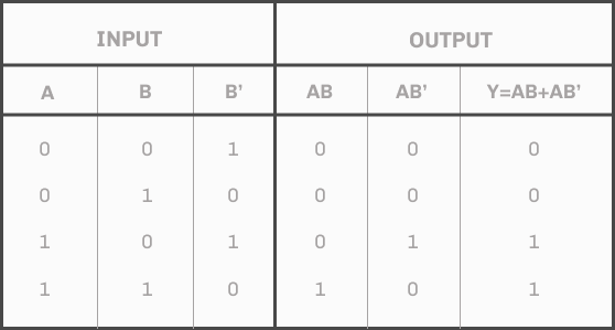
For Boolean expression: Y= AB + AB’
Steps:
- Select Inputs
- Select AND gate and connect inputs (AB)
- Select NOT gate to compliment the input
- Select another AND gate and connect inputs (AB̅)
- Select OR gate and connect the output of AND gates to its input
- Connect output at OR gate and see the output according to the truth table as shown.
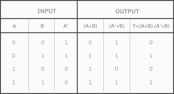
For Boolean expression: Y= (A+B).(A’+B)
Steps:
- Select Inputs
- Select OR gate and connect inputs (A+B)
- Select NOT gate to compliment the input
- Select another AND gate and connect inputs (AB̅)
- Select another OR gate and connect inputs (A̅+B)
- Select AND gate and connect the output of OR gates to its input
- Connect output at AND gate and see the output according to the truth table as shown.
Input & Output
Gates
NOT
AND
NAND
OR
NOR
XOR
XNOR
IC
AND
OR
NAND
NOT
NOR
XOR
XNOR
Disable IC to try boolean expressions
QUIZ
1. What “Quad” indicates with an IC ?
2. The output of EXNOR gate is high if ?
3. A 3 - input OR gate can be best represented using which of following logic (Boolean) expression: ?
4. TTL in Digital Electronics stands for ?
5. Which of following termed as universal logic gates ?
CREATORS
| Category | Theme | Activity |
|---|---|---|
| Electronics Engineering | Digital Electronics | Understanding logic gates using simulation |
Activity Type
Simulation/Tutorial
Principal Investigator (s)
Dr. Anuj Krishna
CSIR-National Physical Laboratory
Contributors
Dr. Anuj Krishna and entire Team JIGYASA, CSIR-NPL
 Presented by CSIR NPL